Free: GMM 3D Printed Quad Sticks - Assembly Instructions

Status
Not open for further replies.

takbok

Well-Known Member
Thank you for purchasing a quad stick kit. Here are some assembly instructions.

Don't cut garden stakes until you're happy with the height you require. Measure twice, cut once!

Parts Required:

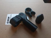
  1. GMM Quad stick kit For Sale: - GMM Pauperflex DIY Quad Stick Kits 3d printed DIY quad sticks
  2. 4x Green Garden Stake 1800mm x 16mm Garden Stake
  3. 2 part Epoxy adhesive https://www.screwfix.com/p/no-nonse...OKjIx793J7BXkuga-9caAlfTEALw_wcB&gclsrc=aw.ds
  4. Hacksaw with fine 32tpi blade
  5. Measuring tape
  6. Insulation tape / sellotape

Assembly steps:

  • Choose front cradle height (this is the flat cradle). This should be about level with your mouth, or to suit your preferences. Measure another brand of sticks if you want to compare. Longer is better if multiple people will be using the sticks - sticks are easily splayed a bit more to suit shorter heights.
  • Front Stick Length = Front Cradle Height - 70mm
  • Rear Stick Length = Front Cradle Height - 165mm
  • (Rear Stick Length = Front Stick Length - 95mm) - This keeps rear V-cradle below Front cradle so that sticks can be used as twin sticks when not splayed front to back.
1747573207450.png
  1. Tape together both front sticks, mark required length (using tape or marker pen) and cut off only the top/blunt ends. Cutting the sticks together as a pair is easier for hacksaw - light pressure and smooth motion helps avoid blade snagging.
  2. Cut the rear sticks to length in a similar way, ensuring that no plastic plug is remaining in either end.
  3. Roll a screwdriver around in a circular motion in all of the cut ends to deburr / lightly flare the ends for easier assembly.
  4. Push front sticks all the way into opening in rubber feet. Hold sticks close to feet so that they aren't bent when applying force.
  5. Push fit all green rod end stubs into sticks so that they are fully assembled. Check that you are happy with fit and alignment. For aesthetics ensure that yoke screw heads face rearwards, and that bottom hinge screw heads face outwards on each side.
  6. Remove all green stubs now and clean/lightly sand insides of sticks, ready for bonding.
  7. Apply epoxy glue to insides of stick ends and to green rod end stubs.
  8. Fit everything together again, ensuring that alignment is good. For aesthetics ensure that yoke screw heads face rearwards, and that bottom hinge screw heads face outwards on each side.
  9. Wipe off excess epoxy neatly (a damp cloth will remove any spills easily).

If you have any queries then please get in touch and I'll be happy to assist.

IMG-20250517-WA0018.jpg IMG_20250514_082113767.jpgIMG_20250514_082123252.jpgIMG_20250514_082155578.jpg
 
Last edited:
Showing relative positions of front and rear cradles with sticks both opened and closed - the rear cradle doesn't interfere if sticks are used as twin sticks for quick or close shots.

IMG_20250519_182335890.webp IMG_20250519_182356075.webp
 
Carbon Fibre Quad Stick Assembly

Parts Required:


  1. GMM Carbon Fibre Quad stick kit For Sale: - Ultralight Carbon Fibre GMM Quad Stick Kits
  2. 4x 2m lengths of 14mm OD x 12mm ID Carbon Fibre tube 14mm (12mm) Woven Finish Carbon Fibre Tube; 1m, 2m - Easy Composites - Please let me know if you manage to find other good suppliers of tube, and suppliers that offer matte finish tube. OR SEE POSTS LOWER DOWN FOR TAKEDOWN OPTIONS - I can send you parts if you received first batch without these connectors.
  3. Electric drill
  4. Hacksaw with fine 32tpi blade
  5. Small fine cut flat file (optional)
  6. Measuring tape
  7. Insulation tape / sellotape
  8. PZ1 & PZ2 (pozidriv) bits / screwdrivers
  9. Good quality sandpaper (600 grit)

Assembly steps:
  • Choose front cradle height (this is the flat cradle). This should be about level with your mouth, or to suit your preferences. Measure another brand of sticks if you want to compare. Longer is better if multiple people will be using the sticks - sticks are easily splayed a bit more to suit shorter heights.
  • Front Stick Length = Front Cradle Height - 70mm
  • Rear Stick Length = Front Cradle Height - 165mm
  • (Rear Stick Length = Front Stick Length - 95mm) - This keeps rear V-cradle below Front cradle so that sticks can be used as twin sticks when not splayed front to back.
1770392432270.webp
  1. Tape the carbon fibre tubes together in pairs, ensuring that they're aligned flush with each other on one end. Decide on the tube length required from the table in the 1st post, or calculate as described in same post. Mark these lengths with tape on both front and rear sticks. Double/triple check your lengths until you're happy to cut tubes. Front tubes should be 95mm longer than rear tubes.
  2. Check your lengths again!
  3. Cut tubes carefully to length with hacksaw using light, smooth reasonably fast cutting strokes. Square off cut ends of tubes if necessary with flat file and or sandpaper while still taped together to ensure equal lengths. Remove tape holding tubes together.
  4. Drill some test holes in tube offcuts first and test fit on rod ends. Drill holes in both ends of rear (shorter) tubes using supplied green drilling jigs and 4mm drill bit. Place jigs over both ends of tube. Place tube on flat surface like table or floor and ensure flat surfaces of jigs are flat on this surface. Tape each jig to tube using protruding lug. Drill hole through one wall only on each end of tube. Drill high speed and use lightish pressure. Do not drill through opposite wall of tube. Repeat for 2nd rear tube.
  5. Drill through uncut ends of front (longer) tubes using supplied green drilling jigs and 4mm drill bit. Place jig over neat uncut end and drill hole through one wall only. Repeat for 2nd tube.
  6. Decide whether or not you want to leave your tubes glossy. If you want a silky matte finish then wet sand your tubes with 600grit sandpaper until achieving desired finish.
  7. Fit front (longer) tubes to front (flat) cradle. The rod ends are a tight fit so might need some rotating back and forth and firm pressure to get them seated in tube but they should butt up squarely with tube leaving no gaps. Ensure holes are aligned and hole in tube is facing to the front (see pics for reference). Use PZ2 driver to screw in 4mm x 12mm retaining screws - screw in firmly but not too tight to crush carbon tube).
  8. Slide 1x rubber isolator onto one front tube and then retaining clip - choose side to suit yourself (see pics for ref.)
  9. Push undrilled ends of front tubes into rubber feet, ensuring that the feet are aligned and hinges facing rearward. Adjust as necessary for good alignment.
  10. Push rear tubes onto foot hinge rod ends, ensuring that drilled hole faces rearwards. Use PZ2 driver to screw in 4mm x 12mm retaining screws - screw in firmly but not too tight (see pics for ref).
  11. Slide 2x rubber isolators onto rear tube diagonally opposite to front tube with isolator. Push 1x rubber isolator onto other rear tube.
  12. Fit rear tubes to rear (Vee) cradle. The rod ends are a tight fit so might need some rotating back and forth and firm pressure to get them seated in tube but they should butt up squarely with tube leaving no gaps. Ensure holes are aligned and hole in tube is facing to the rear (see pics for reference). Use PZ2 driver to screw in 4mm x 12mm retaining screws - screw in firmly but not too tight to crush carbon tube).
  13. Move retaining clip to desired height and tighten screw gently with PZ1 driver, just enough torque for firm no-slip clamping to tube.
  14. Move rubber isolators into place as shown in pics. Feel free to adjust to suit personal preferences.
 
Last edited:
***SUPERCEDED*** Please see new simpler solution in post #10

Carbon fibre takedown option:

Parts Required:


  1. 8x 14mm x 12mm tubes (Mix and match lengths as to make up required length- 0.5m, 0.8m & 1m lengths are available from Katana Composites on eBay, or a few other online suppliers. Choose gloss or matte finish.
  2. 11.7mm x 10mm tube x 0.5m long (12mm x 10mm tube is apparently a perfect fit according to a customer, so worth trying instead for more precision) https://www.google.com/url?sa=t&sou...kQFnoECBsQAQ&usg=AOvVaw0f4MeLRvpC2wSNnILAckc2
  3. 8x 6mm dia x 6mm Long neodymium barrel/disc magnets N52 6mm x 6mm Disc Magnet 4.74g Pull Force - Magman
  4. Epoxy glue.

Assembly steps:

  1. Glue magnets into both male and female plastic connectors. Ensure polarities are correct for each par of connectors. A small Allen key and a toothpick is useful for placing magnet into bottom of female connector.
  2. Cut 4x 120mm lengths of 11.7mm tube and square off ends with sandpaper. These are the guide spigots
  3. Glue 1 male connector into end of each 11.7mm tube.
  4. Glue female connector into upper ends of 14mm tube sections, pushing each connector into tube with green spacer supplied. Clean off any epoxy drips with wet cloth. Allow everything time to cure.ensire no big drops of epoxy remain that will prevent spigot insertion into tube - I think it will be best to put most of the epoxy inside the tube then a thin layer on outside of female connector.
  5. When all epoxy has dried then place 11.7mm guide spigots into top tubes so that magnets/square connectors connect.
  6. Mark off where 11.7mm tube protrudes from joint.
  7. Remove 11.7mm spigot tube and use mark to position it in lower 14mm tube section and glue it in place accurately . Wipe off any excess epoxy. (Use thin small strips of tape on spigot if you want it to fit more snugly and better centre it in 14mm tube).
  8. That's the takedown tube sections complete - now proceed to the assembly instructions above and cut to length etc.
IMG_20250714_192018475.jpg IMG_20250714_195929411.jpg IMG_20250714_192031967.jpg IMG_20250714_195941517.jpg IMG_20250714_195949019.jpg
 
Last edited:
***SUPERCEDED*** Please see new simpler solution in post #10

Please let me know if anything is not clear and I will assist. I haven't completed a set of takedown sticks myself but done this on request as there has been interest in this.

IMG_20250714_200047758.jpg 1752261806656.png 1752261862028.png
 
Last edited:
5th Leg Kit

I've received a few requests for instructions. I don't currently use a 5th leg myself so have mocked it up on my sticks with some carbon tube offcuts.

  1. 5th leg tube length should be about 100mm shorter than the front (longer) legs - this keeps the 5th leg foot clear of the quad stick feet. If in doubt cut it longer and shorten to personal preference later.
  2. If you use your left hand to open sticks, then mount 5th leg on front RH side stick and vice versa (or whichever side suits you best).
  3. Undo 4mm retaining screw (PZ2 screwdriver) and remove one of the front yoke rod ends. Slide on 5th leg retaining clip and 5th leg hinge. Angle both so that the 5th leg nestles between front sticks neatly and tighten screws (PZ1 screwdriver)
  4. . Hinge should be as high as it can be on the tube, and clip just below quad stick retaining clip.
  5. Tighten up screws etc and push 5th leg into rubber hinge socket. If you're happy with 5th leg length then fit rubber sleeve/s if/where necessary to prevent rattling. Then fit the pointed rubber foot on bottom of tube.
  6. See attached pics for further reference.
  7. Please contact me if you have any further questions.
IMG_20250921_173948274.jpg IMG_20250921_173953114.jpg IMG_20250921_174129177.jpg IMG_20250921_181147828.jpg
 
Last edited:
New Carbon fibre takedown option:

Parts Required:


  1. 8x 14mm x 12mm tubes (Mix and match lengths as to make up required length- 0.5m, 0.8m & 1m lengths are available from Katana Composites on eBay, or a few other online suppliers. Choose gloss or matte finish. See takedown tube length chart in post #3.
  2. 12mm x 10mm tube x 0.5m long (0.8m if you need a 5th leg) https://www.google.com/url?sa=t&sou...kQFnoECBsQAQ&usg=AOvVaw0f4MeLRvpC2wSNnILAckc2
  3. Push button spring clips https://www.ebay.co.uk/itm/25617708...LK&stype=1&var=&widget_ver=artemis&media=COPY
  4. Epoxy glue.
  5. 3d printed drilling guide and 5mm drill bit (contact me if you need these bits)
Assembly steps:

  1. Cut 12mm carbon tube into 120mm long lengths (for the spigots).
  2. Sand 12mm spigots if required for a good fit into 14mm tubes.
  3. Glue these spigots into lower ends of the 14mm tube. You want 60mm glued in and 60mm protruding. Let glue cure in these male ends.
  4. Slip 5mm drilling guide over female/ upper ends of 14mm tube so it's flush with end, with arrow pointing to joint.
  5. You want the connector holes to be aligned with the rod end securing screws on all legs.
  6. Connect male and female tubes, ensuring end of drilling guide is flush with joint. Drill 5mm hole through one wall of female tube and spigot tube in one operation. (Hole to be 30mm from end of spigot)
  7. Remove drilling guide and open up holes with the drill until the push button spring clip fits the holes easily.
  8. Insert the spring button clip into the male spigot (attach a small cable tie or string to it if you want to be able to pull it out or position it easier) . If it doesn't fit properly, sand/file the rough parting off pip on the end of the button. If the spring tail interferes with the button, then snap off a few mm of the spring tail with pliers.
I'll add a few pictures in due course.

IMG_20251119_082230565.webp IMG_20251119_082038291.webp IMG_20251119_082109941.webp
 
Last edited:
  • Takedown tube length guide/chart added to post #3. This will give you equal length upper and lower sections when broken down, and also align all the joints.

  • Takedown assembly instructions updated in post #10.
 
Status
Not open for further replies.
Back
Top